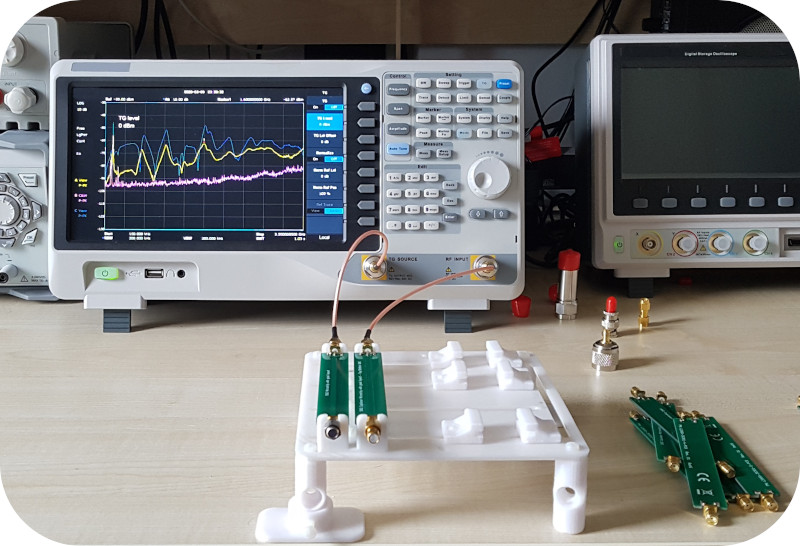
EMC Testing - PCB layout and noise coupling
Engineers do not get surprised by hearing that for precision or RF applications, the PCB must be considered as an electronic component part of the system itself. Each trace routed on the PCB is part of the signal chain and must be carefully designed. This perspective should be actually taken beyond the precision and RF applications, indeed stringent regulations, such as the CISPR standards, apply to any electronic system. CISPR standards cover automotive, industrial and commercial systems and are used by different countries, such as Europe and US, as basis to validate the conformity of a certain electronic system from EMC (Electromagnetic Compatibility) perspective. In this article it will be shown how different trace layouts made on a standard FR4 PCB, may drastically affect the system radiation that may compromise the end product certification, either from conducted or radiated tests perspective. The article will highlights how a PCB should be carefully designed as part of the system, whatever the application would be, to make sure that you achieve the right performances but also you will comply with the EMC standards required for the FCC and CE marking.

